This page is generated from
docs/axonometric.md— edit it there.
Deprecated. The axonometric view is illustrative only and is removed in 2.0 — ArchLang draws plans. See ADR 0021.
The axonometric view
archlang compile plan.arch --view iso draws the building the plan describes, instead of the plan.
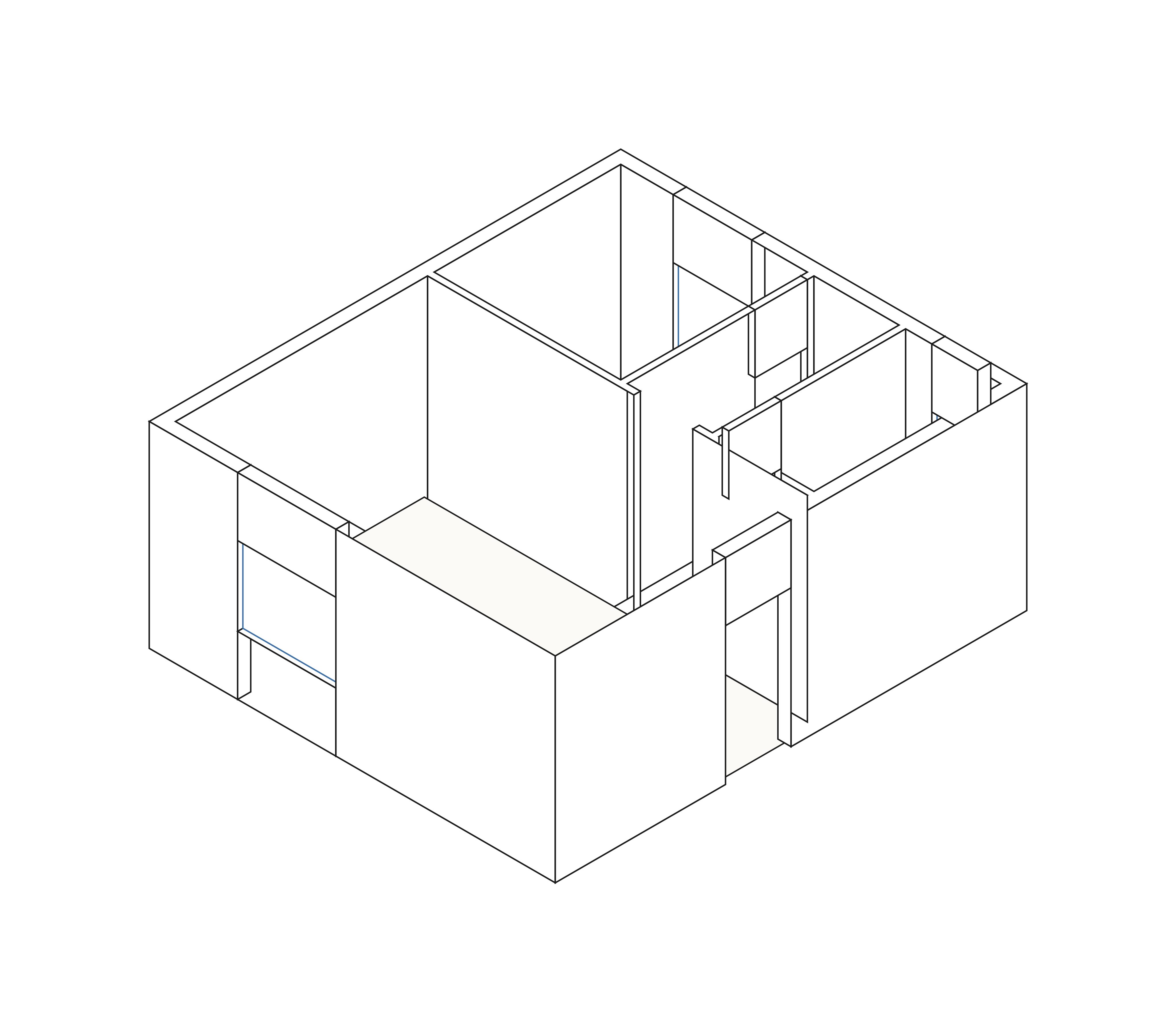
It is the same source, the same compiler and the same Scene: extruded walls with their doors and windows cut, floor plates, and every storey stacked into one picture. Because it produces ordinary Scene primitives, every export ArchLang has already works — -f svg, -f pdf, -f png, -f dxf.
archlang compile house.arch --view iso  -o house-iso.svg
archlang compile house.arch --view axon -o house-axon.pdf -f pdf
archlang preview house.arch --view iso  -o house.png
What it is NOT
It is a picture, not a drawing. That sentence is the whole design, and every limitation below follows from it.
- Nothing measures it.
archlang describeandarchlang linttake no--viewand never learn it exists — no area, adjacency, circulation route or diagnostic is derived from a projection. If you want a number, ask the plan. - It carries no scale, no title block, no north arrow and no dimensions. All four would make it look issuable, and one of them would be false: an arrow points at a compass direction on a drawing whose plan has been turned, and a scale bar measures an axis the projection foreshortens. A plan's
paperdeclaration is ignored here. - No roof. ArchLang stores an eaves outline, not a pitch, so there is no datum from which to build a roof surface. Inventing one would be approximating where the language refuses — the same reason
roofdeclines anarcedge. Deferred by name. - Only walls and floor plates are solid. Everything else a plan can carry is left out, and the list is complete rather than indicative: furniture, columns,
stair/elevator/escalatorshafts, outdoor ground, fences, the site boundary, wall hatches, and every annotation layer — room labels, areas, dimensions, axes, schedules and legends. Some of those are annotation, which a pictorial view has no business carrying; the rest are deferred. A column is the nearest of them: it is already a solid with a footprint and a height, andexamples/museum.archdraws eleven of them in plan and none here. - It has no hidden-line algorithm. Faces are opaque and drawn far to near, which is the classic painter's method. It reads correctly on ordinary buildings and can put a face on the wrong side of another where two solids interpenetrate.
- A curved wall shows its facets. Arcs are flattened through the compiler's one tessellator before they are projected, and each chord becomes its own stroked quad, so a bay reads as if it were mullioned. That is a cost of culling per chord — which is what keeps a curve that turns away partway from being drawn or dropped whole — and it is cosmetic, not a wrong answer. The plan view still draws true arcs.
The two presets
There are exactly two, and no free angles.
iso is a true isometric: the three axes foreshorten equally, the vertical draws vertically, and each plan axis leaves the horizontal at 30°.
axon is the 30°/60° plan oblique an architect calls a planometric: the plan is rotated on the page and kept at true shape and true size, and heights rise straight up, also true size. A plan drawn this way can still be measured with a rule and a protractor — but the view as a whole is still illustrative, and nothing reports off it.
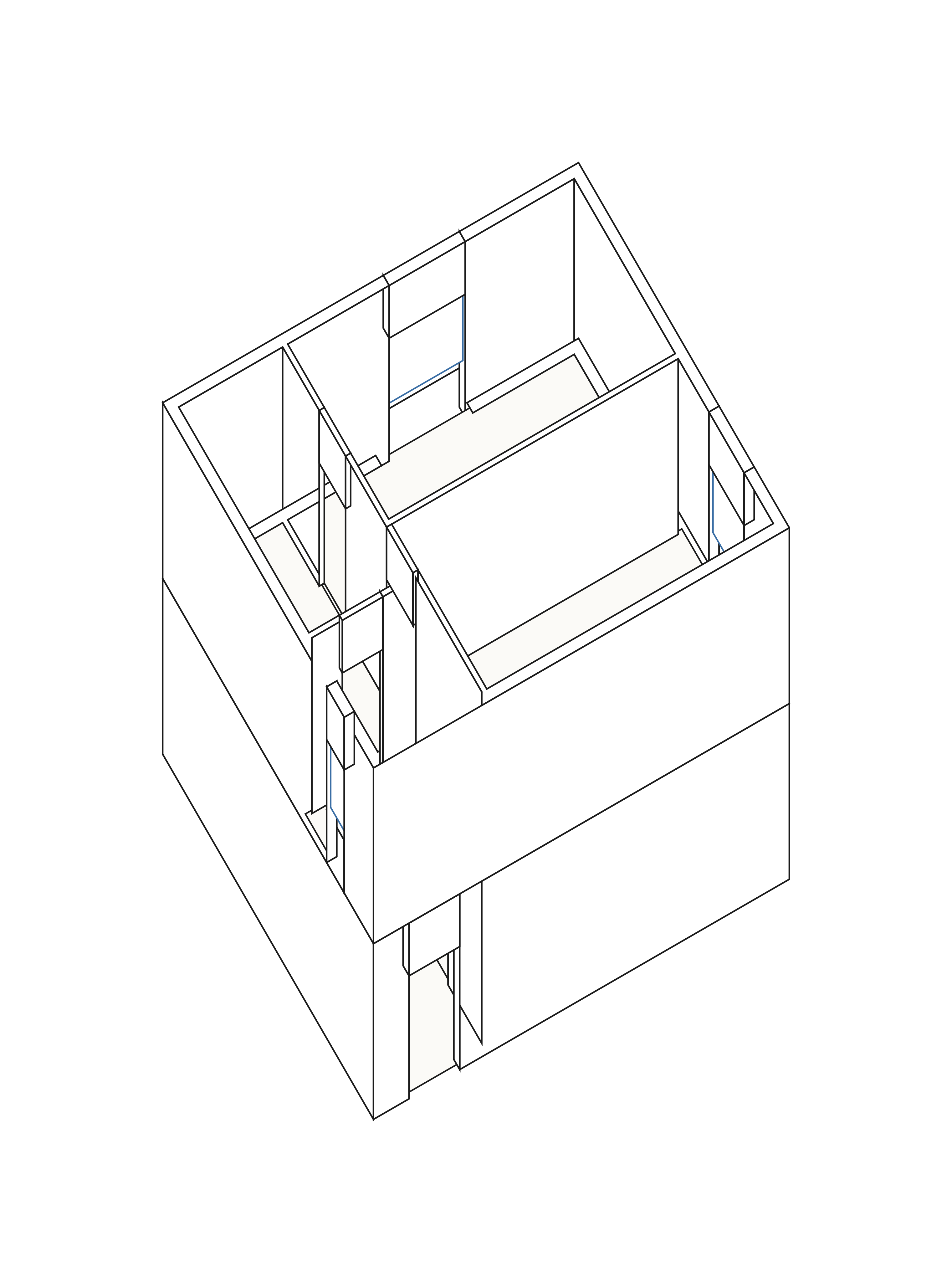
Both look from the plan's bottom-left and above — the south-west, reading the page as a map with north at the top. That is deliberate and shared: switching preset changes the drafting convention, never which corner of the building you are standing at.
The constants
Both cameras are written without trigonometry. Math.sin/cos/tan/atan are implementation-approximated in ECMAScript, so two engines may differ in the last bits, and ArchLang's whole verification system rests on byte-identical output. Math.sqrt is exactly rounded by IEEE-754, so every constant is a square root.
With plan x running right, plan y running down, z up, and screen y down:
iso | axon | |
|---|---|---|
| screen x | (x + y) / √2 | (√3·x + y) / 2 |
| screen y | −(x − y + 2z) / √6 | (−x + √3·y) / 2 − z |
| depth (larger = farther) | (x − y − z) / √3 | (x − √3·y − 2z) / (2·√2) |
iso is a yaw of −45° with a pitch of atan(1/√2); axon a plan rotation of −30° with heights unforeshortened.
What the view draws, and where the geometry comes from
It computes no footprint of its own. Every horizontal outline comes from the part of the compiler that already owns it, so the picture and the plan cannot disagree about the building:
- a wall solid is the joined wall outline — the same edge loops the plan view lowers, taken before they are narrowed to a drawing primitive. Junction trimming, exact mitres and opening subtraction arrive unchanged;
- an opening's hole is the same cut the plan subtracts, and the glazing band is that cut asked for a wall 20% as thick — which is right on a curved host, where an inset is an annular sector rather than an offset rectangle;
- a floor is the room's own ring: its polygon when it has one, its rectangle otherwise. A
voidin the room becomes a hole in the plate.
Walls are grouped by their resolved height, so a plan where every wall is the same height — which is every plan that writes no height clause — is one seamless solid with its courtyards and its holes already cut.
Openings get their real millimetres from the vertical datum, never a fraction of the wall. A window is solid from the floor to its sill, glazed from sill to head, and solid again from head to the top of the wall; a door and a cased opening get the header alone. Those are the same numbers archlang describe --json reports under heights.
CAD layers
The view draws on three layers of its own:
| layer | what |
|---|---|
V-3D-WALL | every extruded wall face and cap, and the blocks that fill an opening back in |
V-3D-FLOR | the floor plates |
V-3D-GLAZ | the glazing bands |
V- is deliberately outside the A-/L-/C- discipline namespace the plan view uses. A CAD user freezes by discipline, and an illustrative view is not a discipline's drawing — putting an extruded wall on A-WALL would make it appear and disappear with the architectural plan it is not part of. A DXF export declares those three rows only on a drawing that actually uses them, so a plan DXF is unchanged.
Refusals
--view is on compile and preview only. It is not on watch (a watcher exists to re-render the plan you are editing) and not on batch.
Four combinations exit 3 with a usage error rather than quietly falling back:
- an unrecognised value, with a did-you-mean;
--viewwith-f txtorpreview --ascii. The ASCII backend draws a plan — it identifies a room as a polygon on the floor pass — and would print a meaningless grid from a projection;--viewwith--level. A multi-storey plan renders as one drawing of the whole building, so-o house.svgwrites exactly that file rather than onehouse.L<n>.svgper storey, and there is no per-storey page for--levelto select;--viewwith--overlay. An overlay draws a measurement — circulation routes, bottleneck markers — and nothing measured is drawn on a projection.
From the library
import { compile } from "@chanmeng666/archlang";

const { svg, scene } = compile(source, { view: "iso" });
view is folded into the compile cache key. When it is absent every byte of every surface is what it was before the option existed, which is pinned over all thirty shipped examples by test/iso-byte-identity.test.ts.